Project
Multi-Model Multi-Phase Cause-Effect Chain Simulation in Direct Injection Engines
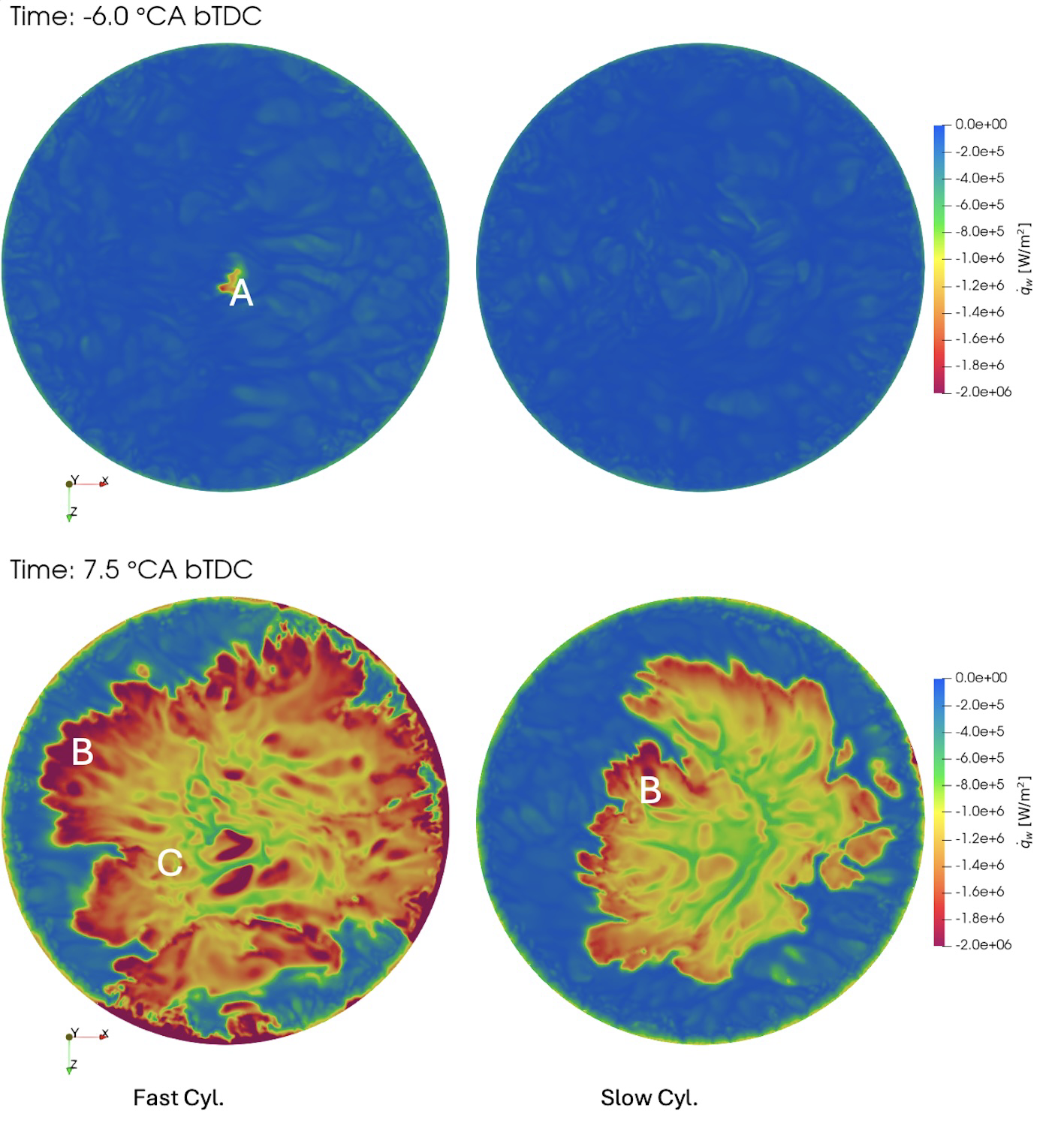 Figure 1: Wall heat flux on piston surface at different crank angle times for a fast and slow combustion cycle
 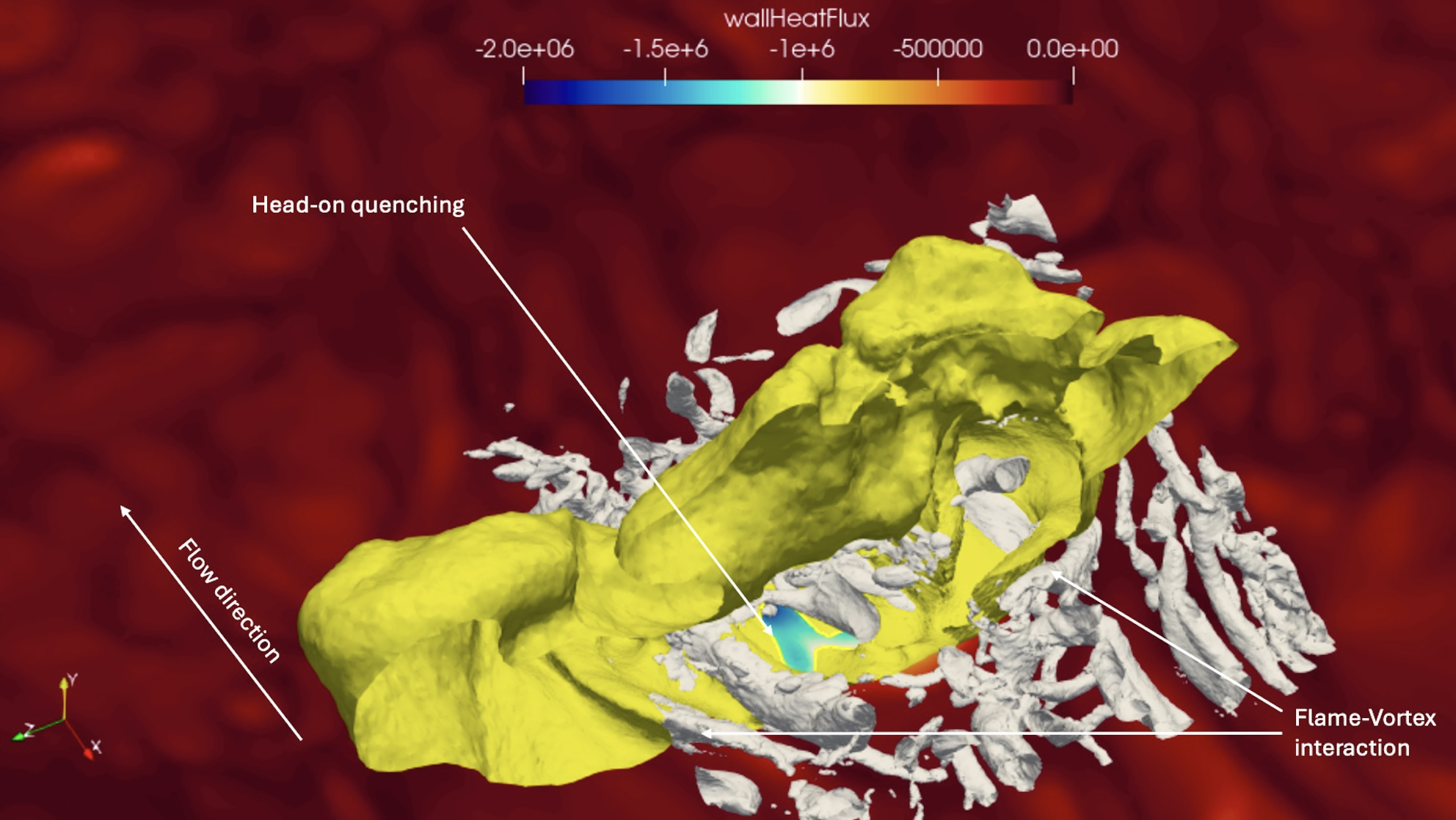 Figure 2: Flame-wall interaction zoomed in on the piston top. Yellow is the flame iso surface. The background colormap shows the wall heat flux. Vortices are visualized using the Q-criterion (grey)
 Project Details
Project term
May 1, 2023–August 8, 2024
Affiliations
TU Darmstadt
Institute
Institute for Simulation of reactive Thermo-Fluid Systems
Project Manager
Principal Investigator
Methods
In this project,the open-source finite-volume, cell-centered CFD framework OpenFOAM was utilized. To simulate engine behavior, an in-house library called TFMotion was integrated into this framework. TFMotion facilitates efficient mesh generation and manages dynamic mesh motion, which is crucial for capturing the movements of the piston and valves.
The LES turbulence modelling approach was employed in all simulations, necessitating high grid resolution resulting in large simulations with up to approximately 24 million cells for full engine simulation to accurately resolve near wall regions.
For spray simulations, the Euler-Lagrange approach was employed. This method treats the liquid phase (fuel spray) as discrete droplets (Lagrangian) interacting with the continuous gas phase (Eulerian), enabling a detailed representation of direct injection and mixture formation processes.
Combustion modeling was performed using a flame surface density method combined with tabulated chemistry. This approach leverages precomputed chemistry data from freely propagating flames to model the combustion process efficiently. The flame surface density method tracks the flame front, providing a computationally feasible way to simulate turbulent combustion in complex engine geometries.
Results
Large Eddy Simulations (LES) conducted in this project included several setups and operating points of the Darmstadt optically accessible spark-ignited engine. One setup was a flow bench configuration, where the piston was removed and the intake valves were open. This setup was used to study the intake flow and its interaction with direct injection sprays, as well as the interaction between the spray and the intake valves.
Another setup involved motored engine operation, meaning the engine was run without combustion. This was done with an intake pressure of 0.95 bar and an engine speed of 800 rpm to study the piston boundary layer during the compression stroke (i.e. before ignition).
Additionally, a homogeneous charge combustion operating point was used to study flame-wall interactions during combustion.
For brevity, only the results from the fired operation are presented here. Figure 1 shows the wall heat flux on the piston surface for two simulation realizations as the flame interacts with the piston surface. Figure 2 provides a zoomed-in view of the piston top, where the flame, represented by a yellow iso-surface, interacts with the piston. Near-wall vortices are visualized using the Q-criterion, with the background colored by wall heat flux.
Discussion
The findings regarding the boundary layer in the engine indicate that, prior to ignition, the piston boundary layer generally does not behave as predicted by the classical log-law theory of turbulent boundary layers. The engine boundary layer only follows the log-law in the viscous sub-layer but does not exhibit a pronounced linear-log region. Instead, it is characterized by a strong wake region due to the tumble flow motion of the engine. This induces an initial favorable pressure gradient at the piston exhaust side, which inverts to an adverse pressure gradient approximately at the piston’s center. This results in an acceleration-deceleration- detachment flow regime of the piston boundary layer.
In terms of flame-wall interactions, Figure 1 demonstrates the framework’s capability to capture cycle-to-cycle variations. Initially, the flame attaches to the piston in a head-on quenching manner, where an initial spike in the wall heat flux is observed (A). In the slow cycle, the flame has not yet attached to the piston. At a later time step in the combustion cycle, both flames exhibit a side-wall quenching behavior (B), and the wall heat fluxes are high in regions where the flame propagates along the piston surface. Very high wall heat fluxes can also be observed in the post-oxidation zone (C).
Figure 2 provides a more qualitative view of the flame-wall interaction. It shows that the flame is manipulated by vortices, leading to wrinkling of the flame and affecting the location of head-on quenching.
The dataset achieved here can be used for validating CFD models and furthering the integration of CFD into engine research. Future research on the exact mechanisms of near-wall pollutant formation can be built upon the work and experience gained in this project.
Additional Project Information
DFG classification: 404-04 Hydraulic and Turbo Engines and Piston Engines
Software: OpenFOAM
Cluster: Lichtenberg
Publications
Hasenzahl, M. Investigation of near-wall processes in an optically accessible SI-Engine using wall-resolved Large Eddy Simulations, Sixth Two-day Meeting on Propulsion Simulations Using OpenFOAM® Technology, Milano; Italy, March 11-12, 2024
PhD Thesis: Lien, Hao Pin, Spray-wall-flow interaction within a gasoline (2023) https://tuprints.ulb.tu-darmstadt.de/26430/